conveyor_case_study_full_def_-_for_students
APPENDIX
CONVEYOR SYSTEM
1. REQUIREMENTS
1.1. Initial Requirements
A company processes toxic waste which arrives in sealed containers. It is important that the containers are sound and free from structural damage as subsequent processing takes place in the containers. The containers must therefore be checked for structural weakness, any failing the test must be cordoned into a safe area, sound containers should be packed into cages for processing.
A system is required that controls the above process and also produces reports and statistical information for quality control. The quality control function is required at the operator level and is also to be integrated into a factory wide information system. The operator must be physically remote from the actual container processing.
Constraints:
Throughput : Must cage 30 containers a minute.
Error rate : The safety tolerance level should be exceeded less than 1 per 100,000 containers.
: A container within the tolerance level should be
rejected less than 1 per 25,000 containers.
Reliability : Mean time to failure 1 year.
Mean down time 3 hours.
1.2. Operational Analysis
An initial analysis of the problem recognises the distributed nature of the system as shown in the system architecture diagram in figure 1.
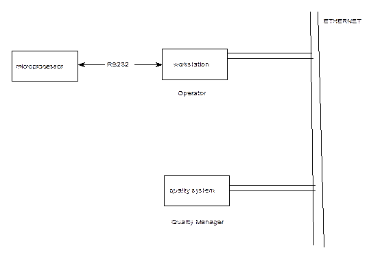 Figure 1 System Architecture
The functionality is partitioned as follows.
Microprocessor Subsystem: controls the conveyor process, receives start/stop commands and process reference data from workstation subsystem and sends process related data to the workstation subsystem.
Workstation Subsystem: Supports operator interface and controls dialogue sequence with microprocessor subsystem.
Quality Subsystem: integrates quality information.
We shall concentrate on modelling the control of the scanning and routing operations in the microprocessor subsystem, since most of the interesting dynamic behaviour is present there. After an operational analysis the following process is proposed. For simplicity, most initialisation and error conditions have been ignored.
1.3. Microprocessor Subsystem Analysis
After further analysis the following model of scanning and routing is proposed.
The operator may input process parameters into the systems and initiate the processing of a batch of containers.
The containers will be transported past non-destructive test scanning equipment and scanned for possible defects, if a fault is detected a mechanised routing arm will route the container off the conveyor into a safety bin. Sound containers will be collected by a cage track mechanism which loads six containers into each cage, before moving the next empty cage into position for loading.
Both scanning and routing operations have probability distributions concerning their completion, mean and variance parameters are assumed similar for both processes.
For safety reasons, scanning and routing must complete, the conveyor must be stopped if a process has not finished before the next container arrives.
Figure 2 shows the process hardware.
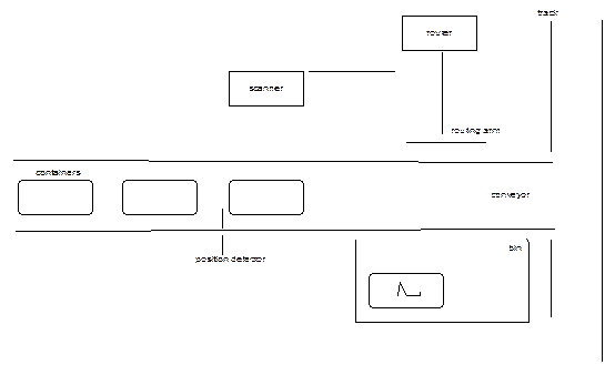
Figure 2 Process Hardware
Process Hardware
Scanner: Scans the container with X-rays to produce a picture frame of data every 1m/s. The sensor equipment moves along a track parallel to the conveyor during each scan. A ‘stop scan’ message causes the sensor equipment to travel back to its start position. A ‘static’ message stops the movement of the sensor equipment.
Conveyor: Transports containers at v m/s.
Containers spaced at d m - where d/v is time when 90% of scan/route complete.
Position Sensor: Signals the arrival of a container.
Router: Receives position co-ordinates. Each set of co-ordinates requires a minimum of 10m/s to complete. For safety, the router is required to signal that a container is in the safety bin correctly.
Cage Track: Cages containers that have passed testing and moves the cages onto the next stage of processing.
Figure 3 shows the corresponding outline of a context diagram for the microprocessor subsystem.

Figure 3 Outline Context Diagram
2. USE-CASE ANALYSIS
This section applies use-case development to the conveyor system example.
The operational analysis defines the following operational sequences with most error conditions and initialisation ignored for simplicity:
‘The operator may input process parameters into the systems and initiate the processing of a batch of containers.
The containers will be transported past non-destructive test scanning equipment and scanned for possible defects, if a fault is detected a mechanised routing arm will route the container off the conveyor into a safety bin. Sound containers will be collected by a cage track mechanism which loads six containers into each cage, before moving the next empty cage into position for loading.
Both scanning and routing operations have probability distributions concerning their completion, mean and variance parameters are assumed similar for both processes.
For safety reasons, scanning and routing must complete, the conveyor must be stopped if a process has not finished before the next container arrives.’
2.1 Initial Use-Case Definition
A use-case development usually starts with a declarative textual definition of the major use-cases and their hierarchy in terms of ‘using’ and ‘extends’ relationships. This is derived from an initial operational analysis that has identified possible system configurations.
One convenient way of expressing the derived use-cases is to state a characteristic which defines a scope for the use-case and then identify scenarios within that scope, for example in the conveyor system, the use-case ‘scanning only ’ has the form:
Use-Case - Scanning Only
Scope
The system scans a container, with no route in progress i.e. it is either the first container or the previous container did not have a fault
Scenarios
1. A container is scanned, found to be sound and caged.
2. A scan does not complete before the next container is detected. Stop conveyor,
finish scan, start conveyor.
This type of definition is highly informal, with inspection the only validation technique available.
Figures 4 shows the use-case structure for the conveyor system derived with reference to the operational analysis detailed in section 1.
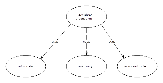
Figure 4 Use-Case Structure for Conveyor System
The ‘Container Processing’ use-case defines the overall sequencing of activities, which is related to the other use-cases via the ‘uses’ relation. The ‘Control Data’ use-case relates to the initialisation of the inspection process and is only considered in outline for completeness. The ‘Scan only’ and ‘Scan and Route’ use-cases define the basic container processing activities of the system. The configuration assumes that containers are scanned successively, if a container is faulty it will be routed as the next container is scanned. The use-case definitions are given below.
1. Use-Case - Container Processing
Scope:
The operator must initially pass process reference data to the microprocessing subsystem, this may change from batch to batch of containers. This behaviour is associated with the use-case ‘Control Data’ through a ‘uses’ relation.
After processing parameters have been set the operator may start the process of scanning and routing. This behaviour is associated with the use-cases ‘Use-Case Scanning Only’ and ‘Scanning and Routing’ use-cases through the ‘uses’ relation.
Scenarios
a. The operator inputs process information.
b. The operator starts the process, processes a batch of containers, and stops the
process.
2. Use-Case - Control Data
Scope
The operator sends scanning and routing parameters to the microprocessor subsystem.
Scenarios
These scenarios deal with the operator setting up the process and will not be detailed.
3. Use-Case - Scanning only
Scope
The system scans a container, with no route in progress.
Scenarios
a. A container is scanned, found to be sound and caged.
b. A scan does not complete before the next container is detected. Stop
conveyor, finish scan, start conveyor.
4. Use-Case - Scanning and Routing
Scope
The system has detected a fault and must remove the container. Note that scanning may be performed on its own but routing will always start with the beginning of the next scan and continue in parallel with the scan. This requires scenarios to cover combinations of termination.
Scenarios
a. A container is scanned, a fault is found so the container is routed off as the
next container is detected (the faulty container will then be in reach of the
router) and scanned. Scan finishes first.
b. As (1), route finishes first.
c. A route does not complete before the next container is detected. Stop
conveyor, finish route, start conveyor.
d. Neither route nor scan complete before the next container is detected. Stop
conveyor, route finishes first, scan finishes, start conveyor.
e. As (d), scan finishes first.
2.2 Use-Case definition with Message Sequences
The above use-case structures may now be specified in more concrete form by describing the associated message sequences at the software interface for each scenario .i.e. the messages between the software and the peripheral environment for each scenario. Message sequences at the software interface level clearly define what combination of software and hardware is to be used to solve the problem and what their respective responsibilities are to be - as already noted, we refer to this as the system configuration. Figure 5 shows some examples of message sequences at the software interface associated with the above conveyor scenarios.
Figure 5 Message Sequences at the Software Interface
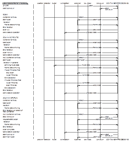
The scenarios are paraphrased down the left hand side with elements of the peripheral environment shown at the top running from left to right, software activity being represented by the ‘system’ element. Signals and messages between elements of the environment during a scenario are shown as horizontal arrows.
Parallel interleaving of signals such as ‘frame data’ and ‘route data’ during scanning and routing are shown using a ‘iterate in parallel‘ control construct. Parallel interleaving is only shown where the ordering of interleaving is irrelevant, any relevant orderings would require another scenario.
The message sequences represent a dynamic view of behaviour, figure 6 shows the corresponding static view of data flow across the software interface on a context diagram.
The isolation of the box track peripheral indicates that it is not considered to be part of the system scope.
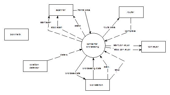
Figure 6 Context Diagram
3. STRUCTURED USE-CASE DEFINITIONS
The use-case definitions of system behaviour may be represented using finite state machines.
In representing the message scenarios as a finite state machine we derive a state structure through which all message scenarios can be represented as finite traversals through the machine. As we are dealing with solutions at the software interface, states should relate to observable partitions of system behaviour e.g. the system is scanning; the system is scanning and routing. The finite state machine will therefore structure the use-cases by assuming a state behaviour of the system and as such will represent an abstract form of behavioural solution. This representation will therefore enable the potential tangle of scenarios to be represented succinctly in a single form. Additionally, through the relationship of signals and states this abstract solution will show the behavioural system characteristics associated with a given system configuration. These characteristics will include what behaviour is expected from the peripherals, at what stage must the system process a given set of environmental information and what the system must remember.
Figure 7 shows the finite state use-case representation for the conveyor system.
The main processing state container processing is reached after initialisation and start signalling from the control data state. In container processing the system waits for a container to be detected and then proceeds to scan in dynamic scan state. The derived structure shows that the system must now make a decision as to whether the container is faulty, also that the decision process may be interrupted by the next container requiring scanning. If a container is faulty, the state route needed shows that this fact must be remembered and when the next container arrives the system must scan and route in parallel as depicted by the dynamic scan and route state. Other states deal with the possible combinations of scan and route termination and the effects of these processes not completing before the next container arrives. Note concurrent operation occurs in the dynamic scan and route state
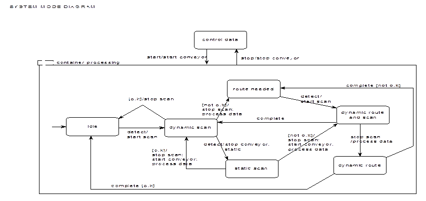 |
Figure 7. Finite State Representation of Use-Case for Conveyor System
- 上一篇:没有了
- 下一篇:没有了